GENERATOR FAILURE INVESTIGATION

GENERATOR FAILURE INVESTIGATION

Written by : Siswanto, Power Generation Engineer

Insulation failure on the generator winding can caused by many factors, this paper provides examples of generator failure on generator 54 MVA, 13.8kV due to the stator winding insulation aging problems, caused by semiconductive layer protection problems, large coil gap resulting endwinding and slot discharge. Our recommendation action to repair the generator is not possible to be done due to the limited schedule.

Generator to be inspected on January 2016 and breakdown on September 2016:

Stator generator inspection / test

  • Visual inspection
  • Coil gap measurement, measured with fillers 0.25mm, 0.3mm
  • EL CID test
  • Stator wedge tightness inspection
  • Stator core tightness inspection
  • Partial Discharge Probe test
  • Dissipation factor tangent delta test
  • Contact coefficient test
  • IR/PI
  • DC Resistance test
  • PDCA (Polarization Depolarization Current Analysis)
  • FDS (Frequency Domain Spectroscopy)

Rotor generator inspection / test

  • IR/PI
  • DC Resistance
  • Static AC impedance
  • RSO (Recurrent / repetitive Surge Oscillosgraph)

Generator to be analysis using Generator Scoring Index method, with the total score 3.3, it is mean the generator condition is very critical.

During in this inspection heavy PD activity were found at endwinding near to core exit, also PD in the slot region and loose wedges found very wide spread.

Temporary repair were performed at the core exit by re-coating the semiconductive and stress grading paint, replacement of the stator wedge is not possible to be done due to the schedule.

However repair is not effective to improve the endwinding, due to the space between top and bottom coil is quite narrow.

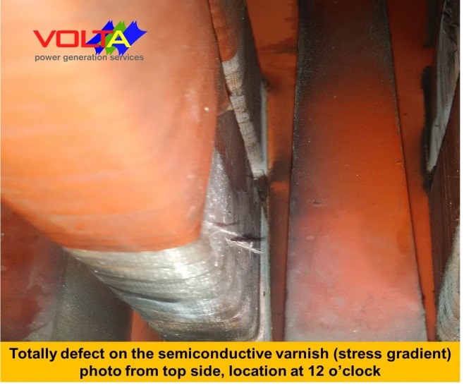
Contact coefficient inspection performing at endwinding by random test, with result the semiconductive layer in the slot is indicate discontinuity.

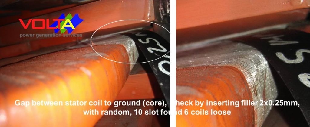
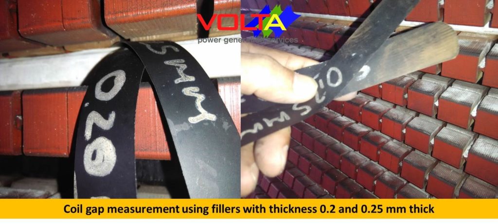
Coil gap was inspected by inserting the conductive fillers with various thickness, 0.25 – 0.5 mm fillers can inserting between core to the coil bars.

Fig.1 Stator visual condition
Fig.2: Coil gap measurement
Fig.3: Endwinding at core exit
Fig.4: Photo end winding at various slot

Fig.4: Photo end winding at various slot

Possibility Failure Root Caused

  • Coil gap: Possibility cause: shrinkage coil insulation material
  • Extreme defective semiconductive coating at endwinding areas: Possibility cause: due to damage of the semiconductive and stress grading layer due to coil movement in the slot and endwinding


Finding abnormalities (failure) level

  • Coil gap : insulation failure level, “High”
  • Partial discharge at core exit and slot discharge : insulation failure level, “Critical”


Summary and recommendation action

Gap between coil to ground (stator core) for more than 0.2mm gap with 10 cm long of coil  length and more than half of coil depth is very dangerous, since this problem will create the PD activities in the slot.

Repair the coil gap and replacement of the stator wedges modified with ripple springs should be planed soon as possible before machine back to operation.


STATOR CONDITION AFTER COIL REMOVAL

September 2016, or 6 months after inspections, generator was fail during in normal operation, stator was rewind by re used the existing coil bars (totally re-insulated), by removing the main wall insulation and reinsulated, with total coils 60 top coil bars, 60 bottom coil bars.

After coil removal from the slot we identified that the stator bars were affected the PD, and semiconductive layer in the slot found were damage.

Fig.5: Re inspection coil after slot wedge removal
Fig.6: Removal the end cap
Fig.7: Visual inspection after stator wedge removal
Fig.8: Coil gap measurement in the slot
Fig.9: Coil bars removal
Fig.10: Removal wall insulation coil bars

Summary and conclusion.

After coil removal from the slot, found semiconductive layer were damaged, heavy high PD activity were identified on the coil bars in the slot.

Large gap were found between coil to the wall stator slot, this phenomenon is possible caused high discharge in the slot.

Corrective action.

All of the stator coil bars to be re insulated by removing and re-insulated the main wall insulation, repair or replacement the inter turn insulation is not possible to be done.

Leave a Reply

Your email address will not be published. Required fields are marked *

Copyright © 2026 PT. Volta Terawindo Bhuwana | Power Generation Services