ELECTRICAL ROTATING HV MACHINE HIGHLIGHT
Written by : Siswanto, Power Generation Engineer
1. INTRODUCTION
Wound stator / rotor windings operating in utility and industrial plants have failed when exposed to the fast rise-time voltage surges coming from unbalance load, drives, breaker, lightning impulse, etc. Machine failure is due to a combination of bad luck in winding insulation process and material quality show that these surges create partial discharges (also called corona) and these discharges may eventually destroy the turn-to-turn and/or phase-to-phase insulation, resulting in premature machine failure.
The fast rise-time voltage surges can lead to an electrical breakdown of the turn insulation in motors / generators stator windings .If the turn insulation is of an insufficient thickness, or has aged in service, the insulation will puncture when a short rise-time voltage surge occurs. Punctured turn insulation allows for a very high circulating current to flow into the affected copper turn, rapidly melting the copper conductors, which, in turn, results in a consequent burning/melting of the slot liner insulation, thus leading to a stator winding ground fault.
2. Stator insulation aging mechanisms
Thermal cycling may cause stresses and movement of whole bars (complete with groundwall insulation) axially relative to their slot, or for quick changes in load the forces from differential expansion may cause internal movement in the bar, between conductors and insulation. The copper windings are the main heat-source when at high load, so these warm up faster than the surrounding iron and reach a much higher temperature, besides having different coefficients of thermal expansion. Mechanical stress and/or movement occurs therefore during changes of load.
There are large forces between conductors even with the currents of normal operation; separate conductors within a bar, separate bars within a slot, and nearby connections in the end-winding region all experience forces that alternate at twice the power frequency and that can damage the insulation in regions where there is looseness that allows movement.
During a short circuit the forces can be many times greater, possibly causing internal damage that initiates longer-term degradation; the bars must be very firmly held in place particularly in the end-winding regions where they do not have the stator iron and slot-wedges to constrain them.
Electrical stress can cause electrical treeing, a change in the insulation material along channels in the field, which may grow enough to cause a breakdown of the insulation.
Partial Discharge activity, although not rapidly damaging to mica insulation when discharges are small, wears the binding material by the effects of local heating, ultra-violet light and production of reactive chemicals such as acids and ozone.


The semi-conducting coating of the stator bars may wear out, due to the chafing from vibration in the slot and from thermal expansion, or due to arcing from lamination short-circuits. The end-winding stress-grading materials may also become less effective with time, leading to surface PD. Tape-applied grading is found to be more durable than paints. Stress between windings in the end-winding region, due to bad design or to movement, can also cause PDs. Conductive dirt on the surfaces of the end-windings, in the high surface field, may cause PDs that wear the surface.
Different ageing effects respectively ageing mechanism caused by electrical, thermal, mechanical, chemical or ambient loads change the properties of the electric insulation system and it comes to a degradation of the material. In the final stage of the ageing the electric insulation breaks down and the equipment falls out. For this reason different methods and measurements for the evaluation of the condition are used.
3. Winding Constructions
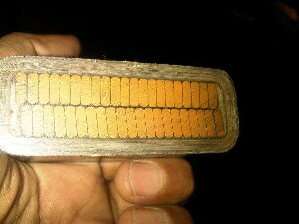
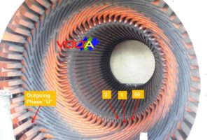
The insulated copper conductor bars that used for winding are distributed around the inside diameter of the stator core, commonly called the stator bore, in equally spaced slots in the core to ensure symmetrical flux linkage with the field produced by the rotor. Each slot contains two conductor bars, one on top of the other (see figure 1-1.Stator winding construction in the slot).
These are generally referred to as top and bottom bars. Top bars are the ones nearest the slot opening (just under the wedge) and the bottom bars are the ones at the slot bottom. The core area between slots is generally called a core tooth.
Stator winding construction in the slot. (courtesy: krempel)


Stator Winding Insulation Construction (courtesy: VRI)

4. Coil Material Properties in History
Stator Winding basically are designed based on to thermal class and voltage rating of the machine. Higher voltage rating need much layer on the winding insulations, insulation construction see fig 1-2 above.
For old machines (build within year 1930s) the manufacture began utilizing asphalt as the bonding agent for the insulation of large synchronous machines.
A asphalt was used to bind mica flakes ( called asphalt micafolium) to form the wall insulation or was used to bond the mica flakes to a tape (called asphalt mica tape), for the modern machine (1950s) the manufacture was gradually replaced by thermo plastic insulation (called thermosetting insulation).
Asphalt based insulation systems are prone to develop a number of problems that are very specific to the thermal class of insulation. A major disadvantage of the asphalt-based insulation is its poor thermal resilience. When exposed to high temperatures, the asphalt develops a sharp drop in viscosity and thus tends to migrate along to the coil to areas of less pressure, its can allowed flow out of the coil.
Thermosetting is better voltage breakdown and thermo class than asphalt-based insulation, Both insulation systems were tapping on the copper bar conductor as many layers, number of layers of tape depended on the tape thickness and rated voltage of the machine.
Better quality of material will allow increased voltage stresses in the ground wall, and its will resulting in thinner insulation’s with better heat dissipation, providing more space for increased copper content.
5. Generator Loading Behavior
5.1. VArs are typically considered to be positive or negative depending on whether they are Lagging or Leading, When 0 VArs are “flowing”, that is considered to be unity power factor (1.0). When the excitation of a synchronous generator at terminal voltage is equal to the bus voltage of the grid, then the power factor is 1.0 and there are 0 VArs “flowing.“
5.2. When the excitation of a synchronous generator at terminal voltage is “higher” than the bus voltage of the grid, then the power factor of the generator will be Lagging (and considered to be positive). This condition is also sometimes referred to as “boosting” the grid voltage, because the synchronous generator is trying to increase the bus voltage of the grid

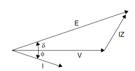
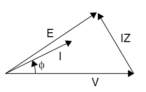
5.3. When the voltage of the generator is “lower” than the bus voltage of the grid, then the power factor of the generator will be Leading (and considered to be negative). generator is trying to decrease the bus voltage of the grid
To cause the synchronous generator’s terminal voltage to be “lower” than the bus voltage of the grid the excitation must be decreased.
Decreasing the excitation causes a distortion in the rotating magnetic field of the rotor, which allows uneven stator winding flux (magnetic) distributions which leads to concentrated heating in the stator end-iron. (There are “two” magnetic fields in a synchronous generator: the rotor’s and the stator’s.) Heat causes problems in many ways, including winding insulation degradation and expansion
6. Winding Vibration Phenomenon
6.1. Winding movement
Stator bars are subject to high possibility of movement in the slot, even small radial or tangential displacement of the bars occurring in the slot will resulting in abrasion of the exterior insulation surface, semi-conductive coating may erode through the ground wall giving rise to partial discharge and then contribute to further deterioration in the insulation, in the case of severe bar motion, mechanical damaged can occur to both the ground wall insulation and core, In turn, the bar will also naturally begin to vibrate at twice frequency
Thermal cycling will also introduce a number of deterioration mechanisms because of different thermal coefficient of the materials, the most comes from expansion and contraction of stator bar copper relative to the core and other restraining components, possible resulting change in size a leading in loosening of the bar in the slot, the stator insulation winding may experience a small amount of shrinkage during high temperature operation over long periods of time in operation, the change in size will also result in looseness.
Recently the only way to monitor stator winding condition is through partial discharge analysis and off line inspection.semi-conductive coating erode and turn short circuit due to undetected loose bar in the slot, resulting partial discharge.
6.2. Stator Bar Movement in relation with the current / power
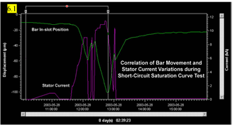
During in normal operation stator winding will movement in the slot, movement for few mm in the slot can cause insulation damaged.
Fig 6.1 Bar movement in relation with current variation
Fig.6.2.Trend graph correlation bar position and active power
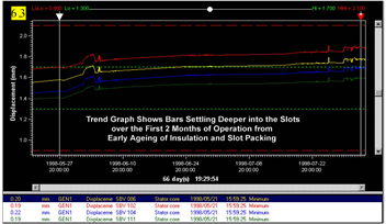
Fig.6.3.Trend graph early aging of insulation and slot packers
(courtesy Vibrosyst)


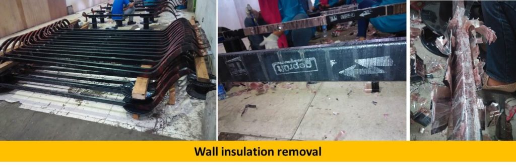
6.3. Stator Bar damaged due to vibration (project experiences)
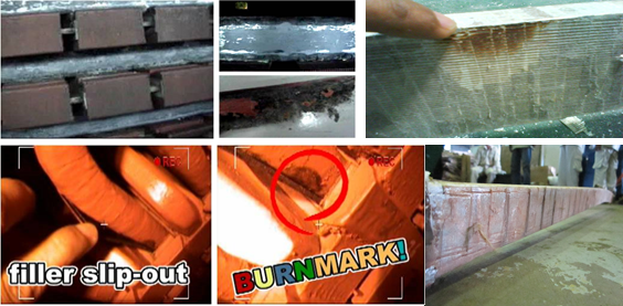
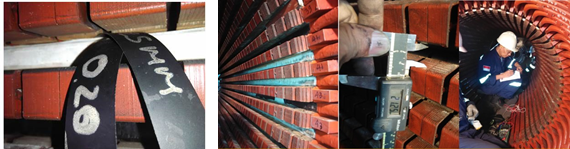
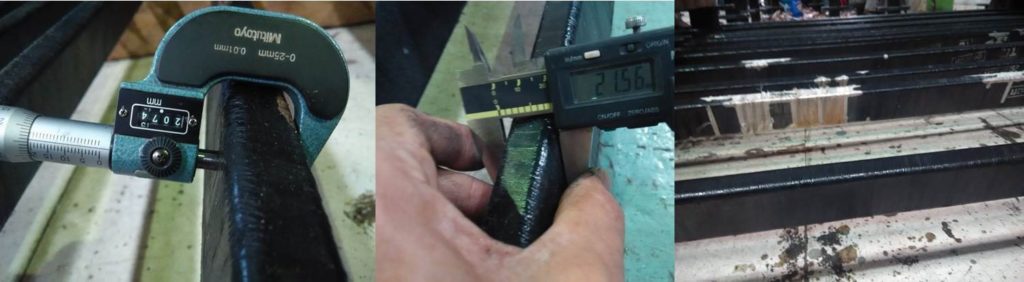
6.4. Stator Bar damaged due to loose contact too large coil gap (project experiences)

7. Slot and Wedges mapping Condition
7.1.Wedge Function
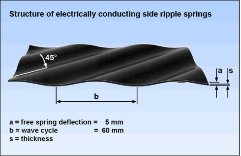
The wedge is one of the main elements controlling the tightness of the coils in the slots, maintain the positive pressure on the coils reduces their movement within the slots to minimizing loss of semiconducting coating and wall insulation.
Slot electromagnetic forces are high and deterioration is common and can be severe. The slot portion of the stator winding is probably the most critical and difficult area of a generator to properly inspect. Most of the important areas of interest are enclosed behind the wedges and the core iron.
7.2. Wedge Inspection
a. Manual tapping:
The common way to inspect wedge condition is to tape on one side of the wedge with a small hammer and sense the amount of movement with the other hand touching the other side of the wedge. Given the response the wedge condition can be classified either as tight, loose or hollow.
b. Measurement Inspection
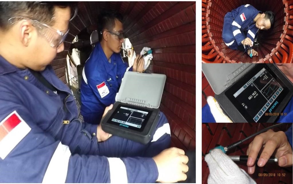
To analysis the wedge condition can performing using a specific instrument such as Leeb D
An impact body with a hard metal test tip is propelled by spring force against the surface of the test piece. Surface deformation takes place when the impact body hits the test surface, which results in loss of kinetic energy.
Surface deformation takes place when the impact body hits the test surface, which results in loss of kinetic energy. This energy loss is detected by a comparison of velocities vi and vr when the impact body is at a precise distance from the surface for both the impact and rebound phase of the test, respectively.
Volta Terawindo Bhuwana | Power Generator Services
Permission to copy this articles pak Siswanto Cahya